| Table of Contents |
Modeling Network Topology
| Click the network button
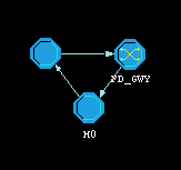
When you choose "DebugModel", the network structure will be displayed on the workspace. Other buttons on the action button panel are mostly used for network model designing.
|
 |
 |
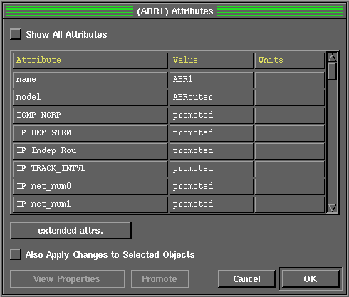
Here is an attributes editor dialog of an ABR router. You may configure the node name, node model and values of attributes. "promoted" in the value field means that the actural value of the attribute are read in from the environment file when the simulation is initializing. |
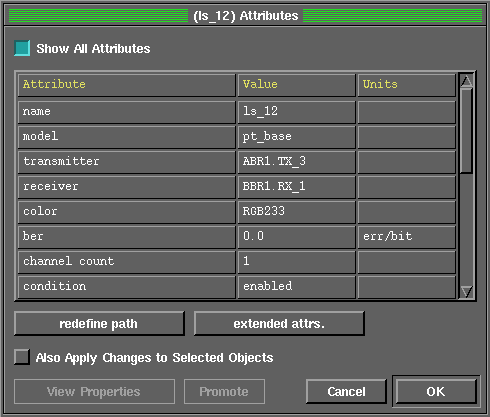
| In our model, data flow is duplex between any two nodes. When configuring connection attributes, you need to select "Show All Attributes" button on the top of the dialog. You can set line's name, connection model, transmitter's and receiver's interface here. Most important, this dialog allow you set bandwidth, transition dalay and error rate of the line. |  |

Clicking ![]() on action
button panel will lead you back to the network model.
on action
button panel will lead you back to the network model.
Opnet will pop up the node structure window
when you click mouse on each node.
| Table of Contents |